
Our Life With The Due
In our recent adventures to build a new prototype synthesizer, that supports a multimode VCF, LFO, and also all the goodies from the SuperPiggy experiment, we were on the look-out for a powerful prototyping platform.. We finally chose the Arduino Due. This post describes our recent experiences with the board.
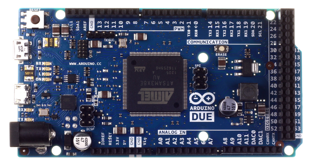
The Arduino Due is the long awaited follow-up of the ever popular Arduino prototyping board. It was released last year to a somewhat chilled audience. It was expensive, at that time a whopping 80 euros, but it featured everything the previous top model had to offer + a processor that is for most tasks 5 to 10 times as fast, a truly huge memory and two real DAC’s. There were differences, though. The main one was the GPIO and PWM voltage. It had dropped from 5 to 3.3 V. This was a drawback in terms of compatibility. And there are more. Most of them we will discuss here in this post. Some of these will be well-known, others not so much.
First off, the IDE that supports the Arduino Due is currently still in Beta. One thing we really noticed was uploads to the board are slow and non-interruptable. That’s about the only thing that’s slow about the Due, though. The thing executes fixed point arithmetic like nothing else. And yes, it also has a decent 32 bit divide instruction 😉
The pins are not only 3.3 volts, but they also cannot source as much current as the old Arduino could. There are even reports of burned out pins, although we have not personally experienced this. Some people report burning out their DACs. In any case, it’s wise to use external amplifiers (a simple transistor may suffice in many cases) to make sure you always have enough power..
A huge convenience of the old Arduino and the AVR microcontroller it hosts, is the fact that it features built-in pull-up resistors. Just set your pin to the INPUT_PULLUP mode and presto, you can hook up a button without any peripheral hardware. On the Due, it’s different. It does have the internal pull-up resistors but they’re as good as useless. Instead of 10 kOhm, we’re now talking about 100-150 kOhm. This means a huge amount of voltage will be divided and there’s a good chance only with minimal interference, that a 0 is read instead of a 1. There are remedies against this: shielding, modifying your read-out functions (f.e. only if it’s 50 times 0 in a row, then it’s a real 0..). But in a prototyping environment shielding is a hindrance, and modified read-outs might still be error-prone. Long story short, get out those 10 kOhm resistors 😉
Another thing is the PWM pins. There are 12 of these, and all of them support 12 bit PWM instead of just the old 8 bit. Also, you can clock these pins pretty high. The Arduino Uno maxed out at about 62 kHz. The Due can do about 300 kHz @ 8 bit resolution. To change this frequency, you need to hack a header file:
Contents/Resources/Java/hardware/arduino/sam/variants/arduino_due_x/variant.h
PWM pins come in two groups:
- PWM
- Timer Counter (TC)
Only pins 6, 7, 8 and 9 are PWM, the rest is TC. PWM can do more like “dead time”, which is required for motor control. For signal processing, however, the TC pins will do fine. Change PWM_FREQUENCY and TC_FREQUENCY to 300000 in that header file and all should be super zappy. Also notice that this DOES NOT break the timing based Arduino calls like delay() or micros(). This is a big advantage over the Uno!
Another oddity we discovered is that GPIO pin 53 is always high for some reason. If any Arduino hackers are reading this.. Do you know why? In any case, with so much GPIO pins, we really didn’t care about that last little piggy that stayed at home 😉
All in all, the Due is a nice piece of work. Probably things will become better when the final IDE is released, but on the hardware front you do need to watch out for the occasional caveat.
The Due is now available for 40 euros and a Chinese clone is about 20, if you can handle the long shipping time..
Pin 53 is wired to 3×8 pin 140, port PB14. As well as potentially being a GPIO pin, it is also CANTX1 – transmit on the second CANbus controller. I suspect that it is currently assigned to this purpose (‘peripheral A’ – datasheet page 1209), so it would be high
I’m afraid that to really understand the Due you need the schematic diagram and the arm3x8 datasheet from atmel. However, it is a really powerful piece of hardware as I think you’re finding out
Cheers
–David
Hi David,
Cheers for the explanation. I also saw something like that. I have the SAM3X datasheet lying around.
Pieter