ST4 DIY – simple boards
These are the smaller and simplest boards in the ST4. Recommended you start here for a good warming up. Most don’t do more than just containing a few sockets and PCB traces.

Note the orientation of the IDC socket. It is mounted on the bottom of the board. and the gap should face outside.
IO Board (MIDI and USB):
A very simple board as well, but NOTE: if you are making an ST4 for rack mounting. DON’T solder the USBHIDINT and USBPROGINT USB A sockets! It’s best to wait until the final assembly and then use Molex connetors or solder the USB wires directly to the PCB contacts.

Note the orientation of the IDC socket. The gap should face outside like shown in the photo above.
Note: The USB A sockets have a central ‘pin’ underneath. In order for the sockets to fit flush with the PCB, just cut these pins.
Power board
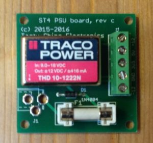
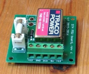
The power board is basically a DC/DC converter board to generate regulated +12V and -12V from an unregulated 12V supply. It also features a fuse to keep the ST4 safe: some people like to hook up negative polarity AC/DC adapters. This will cause the fuse to blow.
Parts:
– Fuse: slow blow, 2.5A
– Diode: 1N4004
– integrated DC/DC converter: TRACO THD 10-1222N
– 5 pin screw terminal: TE Connectivity 282836-5
Note there are 2 unused pins on the screw terminal: 5V and 3V3 are already generated by the Arduino Due, so are obsolete (This is an inheritance from an earlier ST4 design).
Note also that the TRACO is newer than the PCB footprint. It has an additional pin 1 for a standby function. You can just clip the pin. It’s not necessary for the ST4.
The assembly itself is trivial. Just make sure it looks like the photos.


