ST4 DIY – Voice Board
The voice board controls voice parameters like waveform, tuning, and also instrument settings, LFO’s and the sampler and bit crusher. It can also be used for navigation through menus.
Just to avoid a misunderstanding: the board does not have its own analog circuitry for LFO generation or any other signal processing. LFO and voice generation are done inside the microcontroller unit (MCU) onboard the Arduino DUE board.
The voice board merely provides button push signals encoded as a bitstream and decodes a similar bitstream to turn LED’s on and off.. and it provides the analog signals from the potentiometers.
The total bill of materials is listed below:
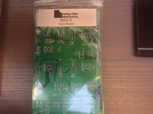
Your voice board kit should look like the following photos:

TODO: moar photo
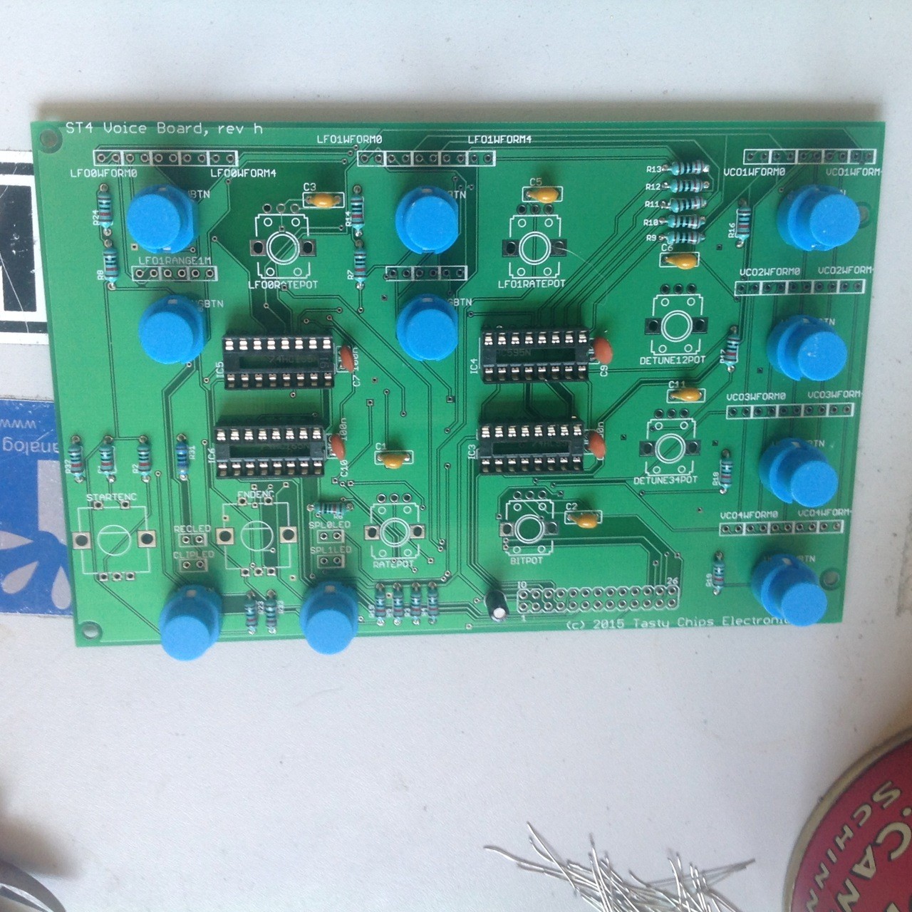
Start with the lowest components. In this case those are the resistors. Group these by value, so start with the 10k’s, then move on to the 2200’s (note that on rev h these are corrected with a cd marker from 220->2200!) and finish up with the three 220’s (same story, also corrected by hand). About the corrections: Please follow the values written on the PCB, the photos may have different R’s soldered! These corrections should be gone in rev i.

Next up are the IC sockets. Beware that these are polarized! Use the correct orientation and align them with the silkscreen! For easier soldering just bend the socket pins so that the sockets are now effectively stuck to the PCB and then just flip it and solder 64 all pins in one go.
Now do the caps. The four ceramic 100 nF’s (marked 104) should go next to the IC’s. The six 1 uF’s (marked 105) should go next to the potentiometers. These have names: C1, C2, C3, C5, C6, C11. NOTE: rev h does not have the values noted on the silkscreen!
Optional: solder the 10 uF elco next to the 2×13 IDC connector. It’s not necessary, but might reduce noise. If you do: beware this is a polarized part. And if you use your own elco: it should be 1 cm high, maximum!

Next up are the buttons. These are the HIGHLYWELL KS-01B blue thingies. Mind the orientation. The flat side should be on the right! Also make sure that you push them all the way down before soldering, to get them exactly perpendicular compared to the PCB.. Otherwise they’ll be hard to fit through the front plate!
The LEDs. There are 40 of them. 38 are clear blue and 2 are orange. The orange ones are for RECLED and CLIPLED (see the PCB lower left corner). All LEDs have the same orientation. The silkscreen thin line indicates + (long leg), while the thick line means – (short leg). Looking at the PCB from the top, all long legs should be on the left side!


LED fitted. Look closely at the LED lens to see the diagonal “gap”. This can also be used for orientation even when the legs are cut and soldered.


We continue with the potentiometers. 6 of these. Take care that these are _without_ detent. I.e. normal continuous potentiometers, _not_ the balance type potentiometers that are used on the other. Just make em snap and solder.
Now to add the two rotary encoders. Because they are lower than the potentiometers, but we’d like to have them at the same height, we suggest to _not_ snap them through the holes. Instead, just solder them on top of the contacts and holes and all should be fine.
The final step: solder the 26 pin IDC socket to the bottom of the PCB. Mind the orientation. the gap should be towards the outside of the PCB!
All done!


