ST4 DIY – End assembly
This is the final page in the ST4 DIY manual. It shows you how to hook up all boards, how to test, and how to put everything into the casing.
Hook up the SD board
This is Exp board rev i only. Higher revisions have a IDC connector for the SD board.
If you have exp board rev i you will need to solder some pins to a 6 pin ribbon cable. These are marked on the exp board. Here are the mappings from the exp board to sd board:
| EXP | SD |
| 16 | MOSI |
| 17 | MISO |
| 20 | CS |
| 53 | SCK |
| GND | GND |
| 3V3 | VCC |
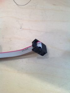
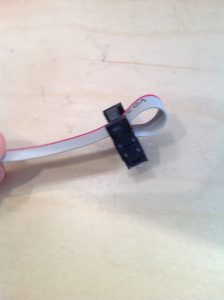
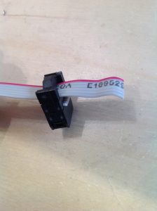
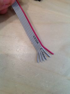
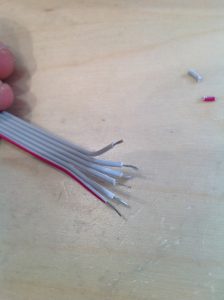
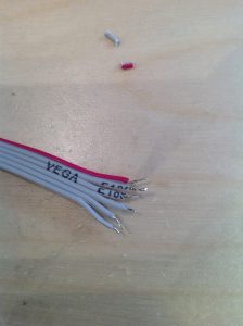
It’s good to cut one side of the supplied IDC cable, as close to the connector as possible. then strip the ends and solder them like shown in the pictures.

Please check the markings (GND, MISO, etc) on the SD board silkscreen and use the beeper on your multimeter to verify connection.
12V Power cabling
It’s time to solder the power board to the power switch and to the 2.1 mm socket. Make sure the center of the 2.1 mm socket is hooked to the positive side. The other terminal should be GND.

Hooking up the cables
Except for the SD board in the EXP rev i setup, all boards are easily connected. Every socket is labeled and can only be connected in one way (if you soldered the IDC sockets in the right direction, but the earlier pages saw to that). For your convenience, pictures are provided of a setup, ready to go.

There’s only one exception in the entire system: The mic board and voice board are on the same ribbon cable. This cable has got three IDC connectors instead of 2. It can be connected in various ways. The picture below has the Mic board in the middle, the picture above has it at one of the cable endings. Either way is fine.

The Exp board is connected to the power board by +12,-12, GND on the screw terminals. Make sure you use a bit thicker wire here, since 0.5A may run through here.
Electrical test
Power the system on as is. No casing yet. It’s best to test everything. Just hook the power brick up to the 2.1mm socket and flick the power switch.
A virgin display can be glitchy. For some reason unknown to us it helps to push down on the pin header (connection between EXP and display) a little and slightly wiggle the screen. After a while or a couple of resets it will stop glitching and function properly. What you should see is a boot animation that builds up the ST4 logo:

Look at the first chapters of the User manual to test features like the tracker and instrument editor, and all the knobs..
.. and come back here when there’s no trouble to be found.
Of course, in all those hundreds of soldering points, there should always be a couple of bad ones. In our experience, the control boards (voice, mod, vv) and smaller ones are rarely a problem. The exp, vca, and vcf boards can be tricky. To make troubleshooting easier for you we’ve added pictures of the layouts with connector pinouts included.

Connectors (from left to right):
VCF_IN:
GND: ground
S1-S4: VCO outputs, tracks 1-4
VCF_CV:
GND: ground
V+: +12V supply
V-: -12V supply
C1-C4: VCF cutoffs for tracks 1-4 [0..5V], 0V means completely closed, 5V completely open
R1-R4: VCF resonances for tracks 1-4 [0..5V], 0V means no resonance, 5V means max resonance
VCA_CV:
GND: ground
V-: -12V supply
V+: +12V supply
L1-4: left CV channels [0..5V], 0V means completely open, 5V completely closed
R1-4: right CV channels [0..5V], 0V means completely open, 5V completely closed
VCF_MUX:
GND: ground
V+: +12V supply
V-: -12V supply
A0-3: MUX signals (lower bit for tracks 1-4)
B0-3: MUX signals (upper bit for tracks 1-4)
Please understand that the A and B signal make the 2 bit MUX control for one channel. These 2 bits control the VCF modes: 0 (00)->lowpass, 1 (01)->bandpass, 2 (10)->highpass, 3 (11)->bypass.

SIG_IN:
GND: ground
S1-S4: VCO outputs (VCF inputs), tracks 1-4
VCF_CV:
GND: ground
V+: +12V supply
V-: -12V supply
C1-C4: VCF cutoffs for tracks 1-4 [0..5V], 0V means completely closed, 5V completely open
R1-R4: VCF resonances for tracks 1-4 [0..5V], 0V means no resonance, 5V means max resonance
VCF_MUX:
GND: ground
V+: +12V supply
V-: -12V supply
A0-3: MUX signals (lower bit for tracks 1-4)
B0-3: MUX signals (upper bit for tracks 1-4)

VCA connectors:
CV (12 pin):
GND: ground
V-: -12V supply
V+: +12V supply
L1-4: left CV channels [0..5V], 0V means completely open, 5V completely closed
R1-4: right CV channels [0..5V], 0V means completely open, 5V completely closed
Signal in (6 pin):
CH1..4: audio inputs for each track. This should come from the VCF board.
Casing assembly
First of all, it’s time to remind you that the ST4 comes in two different flavors: rack mounted, and desktop. By correctly positioning the PCB’s the ST4 can be configured as one or the other.
Contents of casing kit:
Bag I:
* 1x 2.1mm barrel socket, Bag I
* 12x M3 120 degree countersunk bolt, Bag I (90 degree also works)
* 19x M3 cheese head bolt, Bag I
* 4x M3 nut, Bag I
* 2x M3 2cm spacer, Bag I
* 1x mini rocker switch, Bag I
* 6x mounting bracket M3x10x11x7, Bag I
* 2x Sifam soft touch rotary knob, Bag I
* 35x Sifam soft touch knob with blue indicator, Bag I
* 4x Slider knob, Cliff CS7A, Bag I
Bag J:
* 1x perspex window, Bag J
* 1x 3.2″ display, Bag J
* 1x TODO?
Casing:
* 1x ST4 casing container part, including 6 pre-mounted anti-slip pads
* 1x ST4 front plate
TODO: exact model numbers. Note that 4 of the countersunk bolts are used to screw on the front plate, for safe transportation.
The casing consists of two parts. The “container” and the front plate. The container has a bottom side (the big side) and a back side. Both have cutouts.
Front plate assembly is almost trivial: just glue in the perspex window. We recommend super glue. The usual warnings apply: don’t get this stuff on your fingers, and leave to dry a couple of minutes.
If you want a desktop version, the VCA board’s phono sockets go through the back plate. VCF and power should be mounted on the bottom plate. The IO board should be mounted on the back plate.
If you want the rack version, the VCA board’s phono sockets go through the bottom plate. The IO board is mounted on the bottom plate. Power and VCF boards are mounted on the bottom.
Note that the IO board requires two “spacer towers” to be constructed. 1 tower consists of a 2cm spacer, 2 brackets and a nut. The spacer tower for desktop mount is slightly different from the rackmount version. See the pictures below:

Desktop mount spacer tower: bolt – bracket – spacer – bracket – pcb – nut

Rack mount spacer tower: bolt – bracket – spacer – pcb – bracket – nut . Compared to desktop mount: the lower bracket goes under the PCB and the brackets are reverse oriented. This was done to get the PCB as close to the corner as possible. More importantly, the internal USB sockets are best to replace with Molex connectors like shown above. Or easier: just solder the wires directly to the contacts.

Most bottom/back boards are mounted using bolts and spacers. The VCA is an exception and can completely be panel-mounted using its 6 phono sockets. Screw on the nuts and presto.

Once all bottom and backplate boards are mounted, you can panel mount the control boards onto the front. These are: voice board, mod board, vv board. These are fastened using potentiometer nuts. Only the mod board has 2 additional bolts to complete the mounting. Be sure to screw nuts on ALL potentiometers, since this adds to the strength of the system.
The SD board is fastened using brackets, bolts and nuts. The cheeseheads are used on the PCB side of the brackets. The countersunk ones are for the front plate.
The mic board is fastened using a potentiometer nut and a minijack nut.
Don’t forget the minijack for the headphone output. Just fasten the nut.
The exp board is suspended on 3 cemented spacers. Use cheesehead bolts to fasten it. The screen needs an additional 2 more. Make sure the cables are hooked up to the exp board and the arduino is tested.
Finish
6 countersunk bolts to go. Lift the lid over the “container”. And screw those bolts into the front plate. All done.
You may now eat your chips!
Epilogue
Tie-wraps! Use them to fasten all the cables together. For best noise performance: keep ribbon and USB cables away from the VCF board!

